September 5, 2018, 8:17 am
One Raspberry Pi Model 2B with Ian Canada Pi Hat i2S isolator unused and brand new.
Price: £65 including postage UK, overseas please enquire
One Rasberry Pi model 2B with Pi2 I2S adapter package, unused and brand new.
Price: £30 including postage UK
↧
September 5, 2018, 8:38 am
Hello Chaps,
Has anyone ever compared those two MC cartridges? I am looking for a MM or MC that is ideal for classical music - large orchestral works - for a reasonable price.
I have had FR, Benz, several Ortofons, Sumiko, Grado, Denon, etc. but I am still not hundred percent satisfied. I am aware that the sound depends on ancillary equipment too. I am using a Klyne 6 series preamp.
Cheers,
Horacio
↧
↧
September 5, 2018, 9:06 am
I'm part of a small band that performs semi-regularly for 200 people tops.
We are 4 musicians that use the following:
4 mics for singing
1 powered classical guitar
1 classical guitar that's powered through a regular mic
We want to buy a PA system.
We were thinking of buying the Yamaha StagePas I600 + 5 SM58 mics for our PA system but then got a recommendation that it wouldn't pack enough power for 200 people (indoors).
A store gave us the following setup:
Mixer - TRX Audio MEN82FX
2X Speakers - TRX Audio Q10-AD
5 PGA mics / SM58 mics
It seems like the store's set up would be more versatile, powerful and even professional then the StagePas, which kinda gives me the feeling of a large loudspeaker (but I might be totally wrong).
The store's setup is also much cheaper then the StagePas.
But, and this might be a big but, I am unable to find any reviews on these TRX products.
Is TRX a solid brand?
Are these products any good?
They come with a 2 year warranty.
Any advice would be great.
Thanks a lot!
↧
September 5, 2018, 10:22 am
I have a Dean Markley CD60 tube amp. 50W 6L6 output stage. Nice little amp. It had bad filter caps which I fixed, but then I encountered extremely high bias currents in one tube and high current in the other.
I determined the extremely high one was probably bad. It was up at 90mA with the other tube at 55mA. I checked for leakage in a coupling cap and don't find anything wrong.
I put a matched set of tubes in and I can not reduce the bias below 45-55mA in both tubes. I can't just change a resistor value to be able to go more negative, since with the pot all the way down it only goes to -55V or so. I can switch it and get the bias from the end of the transformer instead of the tap, but it seems to me that -55V on the grid should be enough to limit the current?
The plate voltage is around 460V, so 45mA is a pretty hot setting. 460x.045= 21W which is only 70% of 30W. I don't usually set anything to 70%, but this one I may have to.
Perhaps I could get a set of graded tubes that have a low bias current, but I hate to buy tubes I don't need. I plan to sell it and make a profit. At least that's the plan.
Any ideas on what else I can check that might make the bias current too high? Everything I checked seems OK, and it sounds OK.
[IMG]
![Click the image to open in full size.]() CD120 Page 4
CD120 Page 4 by
Dennis Kelley, on Flickr[/IMG]
↧
September 6, 2018, 1:15 am
i'm trying to load the 830668 woofer in a TQWT enclosure. the project is for Tarkus 3way. However, when i use the calculator here,
mh-audio Tapered Quarter Wave Tube
the line length keeps coming up as 267cm, and folded that in half,i still get ridiculously long box.
is there any other calculators that i can go by? i want the line length to be around 100cm or less
↧
↧
September 6, 2018, 1:32 am
I search for an active replacement for the 2SJ115/2SK405 and only found that IRFP240/IRFP9240 could be a possible replacement? Mouser have them anyway. Is there any else that can replace them that are active an not discontinued?
↧
September 6, 2018, 2:24 am
Are there any technical reasons not to use the classic 4-20mA industrial current loop standard for powering the onboard electronics in a guitar, and delivering the audio signal?
Current loop industrial sensors have existed for decades, yet I can find little information about their use with analog signals that extend beyond the vocal frequency range.
Cable wise you could just use a standard microphone twisted pair cable with a TRS 1/4" jack on either end.
↧
September 6, 2018, 3:52 am
Hello. I am in the market for a pair of used Spendor bookshelf units. Non-production model OK...however, nothing needing DIY repairs. Sorry, I'm too feeble...read that as old. Chicagoland area a plus!. Thanks, civil6.
↧
September 6, 2018, 4:03 am
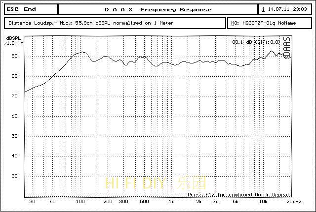
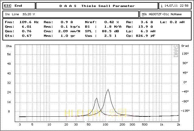
Cut to the chase, I need new woofers.
And this one stands out among the rest due to how low it can go:
Option 1
![Click the image to open in full size.]()
![Click the image to open in full size.]()
However I am concerned about the rising bass response.
Since Audioengine A2 already has its own bass boost that it is known for. I would be fine with either one of the bass boost for a small speaker, but both combined would probably be too much.
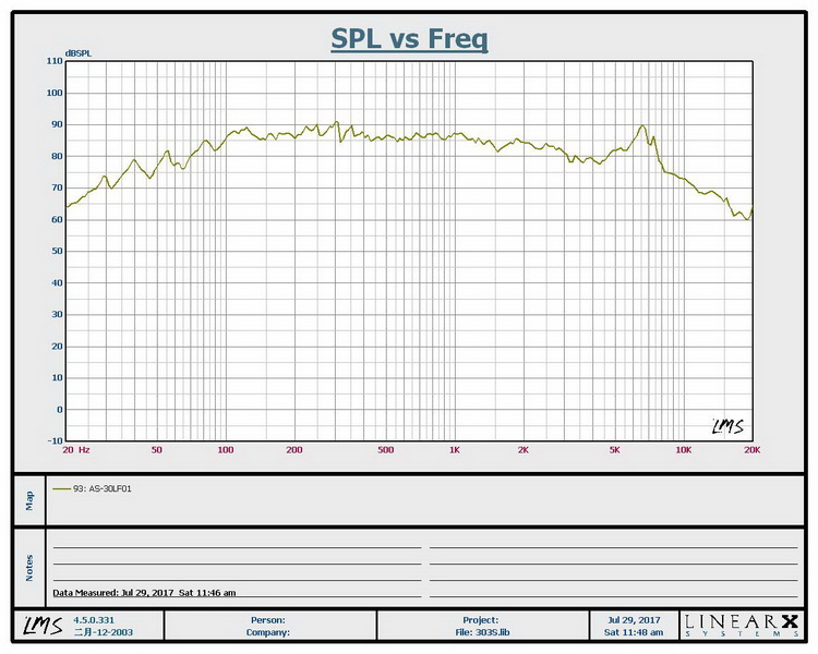
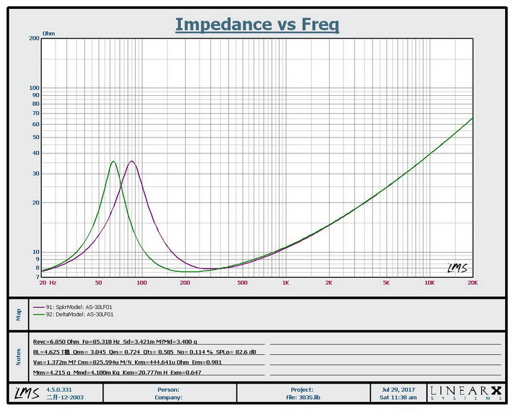
Option 2 - Less bass, higher FS
![Click the image to open in full size.]()
![Click the image to open in full size.]()
Options 3 to 9001 (All roughly around the same feeling) - Bass starts falling at around 100Hz, Fs over 100Hz.
But
this particular unit catches my attention because it does not lose too much 1kHz - 2kHz unlike other 3", including Audioengine A2. It also has a low Fs.
![Click the image to open in full size.]()
![Click the image to open in full size.]()
I understand that these frequency charts need to be taken with some iodine sea salt. My aims are 1) Give the modified A2 as much bass extension as possible (The stock woofer's extension is horrid), but at the same time 2) Fix the rancor pit at 1kHz.
And 3) Avoid changing A2's own EQ if possible. I am fine if the speaker's own frequency response is completely flat, because I run a similar bass boost on my Marantz amp and I love it.
In this situation, which woofer is the best? If not for the rising bass response, I would have chosen the first one due to bass extension. Or does anything with a low Fs work? In that case I can choose option 3.
Thanks a lot.
↧
↧
September 6, 2018, 5:15 am
I am looking for any details or information concerning the crossover schematic for the PMC BB5 passive monitor speaker system.
A layout of the components would be a great help.
Pics of the speaker
here
PM or post if you can help
Thanks
↧
September 6, 2018, 6:18 am
Hi,
So I have been waiting for some time to try a tube circuit, and after buying some tubes for cheap I've had a go at designing a simple common cathode stage.
I've been through Merlin Blencowe's guide and browsed around Pete Milletts page, and also have Morgan's Valve Amplifiers book (or I will have when I turn 40 in 2 weeks).
I've tried to do the loadlines and pick a decent operating point for the tubes, (6N16B) and I feel like the choice of bias point is almost arbitrary, within the limits of Va and Ia, and thus came up with several options.
The variants are Ra between 2 and 4 times the plate resistance, cathode resistance to suit each case.
I've drawn it up and attached to this post.
Can some kind soul take a look and give me an honest opinion?
↧
September 6, 2018, 7:27 am
A couple thoughts to run by you with respect to taming the JBL ring radiators. The first is the idea of adding a small series choke after the 2nd order xover. If chosen correctly we should be able to create a slight bump at the 9KHz suckout with as gradual attenuation above 10KHz. An L-pad could then be used to adjust the over all level.
![Click the image to open in full size.]()
The other idea is adding some dispersion. Instead of the rather complex JBL acoustic lens could we possibly suspend a small parabolic button in front of the tweeter center line to scatter the highs a bit. Something like a phase plug but turned around backwards and suspended in front of the tweeter.
Go ahead, set me straight.
↧
September 6, 2018, 7:42 am
↧
↧
September 6, 2018, 7:49 am
Back in the day many ported enclosures used a simple slot opening with no duct. I have often wondered about that approach but I have noticed in running simulations that such an arrangement looks especially good for drivers with a Qts in the transition region between sealed and BR/horn drivers (eg. 0.4x).
With these drivers the sealed box usually lacks in bass but a normal port has a rather large cross sectional area. With these drivers the length can be very short (just panel thickness) and still have reasonable area.
Thoughts?
↧
September 6, 2018, 8:03 am
↧
September 6, 2018, 8:32 am
I have for sale a matched pair of these tweeters. They are pretty much new. Mounted once with plastic screws so no sign of it. 8 ohm version.
Viawave GRT-145
MRSP is $525 +S&H. I would like to get $400 shipped (+pp fees if you pay not as gift). Thanks for checking!
Attachment 701868
↧
September 6, 2018, 8:58 am
↧
↧
September 6, 2018, 9:14 am
hi i have built this power supply (see pic)as a general unit to use with separate amplifiers that i build , the problem ime having and has vexed me for months!it works fine with most amplifiers apart from lm3886 amps ,and they play for about 5 mins then first one channel stops then the other , the chips do not get hot and have adequite cooling , and they are properly grounded , i allso have another power supply i have made using two separate transformers and it has no problem driving the lm3886amps... it apears that the chips have a protection device (spike) but cooling isnt the problem please if any body can shed some light it would be most appreciated (in laymans terms please as most tech talk baffles me
↧
September 6, 2018, 9:36 am
hey all, so i've got this together, it's been working just fine for some time, however i get a lot of popping and other noise when i connect my RCAs so i'm assuming i've done something wrong here with my grounding. i basically fear i'm going to pop my speakers when i connect and disconnect them so i literally turn off the amp when i do
icepower 500ASP with two 500A hangers is what we are looking at here
i've isolated the rca inputs from the chassis using just some plastic ring washers through the cutouts and fabric washers between the backing and plastic washers
i've only grounded the 500ASP earth to the chassis. comes in from plug, earth goes to chassis, chassis to earth on ASP mains input (120v)
questions:
should there be any other chassis grounds throughout?
should i be grounding the rca inputs to the chassis?
is the earth the wrong ground to begin with?
just looking for some help from the experts. i'm no electrical engineer, just a guy who took a project he probably was over his head on
thanks!
some pics to help:
![Click the image to open in full size.]()
![Click the image to open in full size.]()
![Click the image to open in full size.]()
![Click the image to open in full size.]()
![Click the image to open in full size.]()
↧
September 6, 2018, 11:29 am
A bit of background first. I'm UK based and more used to building and repairing guitar valve amps but thought I'd give a kit a go for playing my Vinyl. I ordered a Douk 6N9P/EL34 kit as I am very familiar with EL34's and have some nice EL34's in my valve collection. I have three valve testers, a Dyna Jet 606 which gets used as a quick go/no go test, an AVO CT160 which I rescued, restored and calibrated and a uTracer3+ which I built and is very accurate indeed.
I knew very little about the quality of the kit or 6N9P valves other than what I read which opinions varied from very good for the price to junk. They ran out of kits, so sent me a ready assembled job. The wiring is neat, but the layout and some of the components leave a lot to be desired. First job - test the valves. I was pleasantly surprised, the diodes are pretty even per side - I've seen worse EL34's sold as "premium" valves.
Here's the results from the uTracer - I would have posted the traces, but the forum insists they are on a URL :(
Comments/ Opinions welcome.
Code:
06/09/2018 11:19:05   uTracer3, GUI  V3.11  Triode Quick Test


6N9Pa  SECTION 1


Test conditions:

Va  : 250 (V)                Swing +/- 25 V (10%)

Vg  : -2 (V)                 Swing +/- 0.2 V (10%)


Test results:

Ia  : 1.73 (mA)              173 % of nominal 1 (mA)

Ra  : 46.88 (kohm)                                              Ra = dVa/dIa

Gm  : 1.49 (mA/V)                                               Gm = dIa/dVg

mu  : 70 (-)                                                    mu = Gm*Ra


SECTION 2


Test conditions:

Va  : 250 (V)                Swing +/- 25 V (10%)

Vg  : -2 (V)                 Swing +/- 0.2 V (10%)


Test results:

Ia  : 1.8 (mA)               180 % of nominal 1 (mA)

Ra  : 45.74 (kohm)                                              Ra = dVa/dIa

Gm  : 1.55 (mA/V)                                               Gm = dIa/dVg

mu  : 71 (-)                                                    mu = Gm*Ra


06/09/2018 11:23:05   uTracer3, GUI  V3.11  Triode Quick Test


6N9Pb  SECTION 1


Test conditions:

Va  : 250 (V)                Swing +/- 25 V (10%)

Vg  : -2 (V)                 Swing +/- 0.2 V (10%)


Test results:

Ia  : 2.02 (mA)              202 % of nominal 1 (mA)

Ra  : 43.28 (kohm)                                              Ra = dVa/dIa

Gm  : 1.58 (mA/V)                                               Gm = dIa/dVg

mu  : 68 (-)                                                    mu = Gm*Ra


SECTION 2


Test conditions:

Va  : 250 (V)                Swing +/- 25 V (10%)

Vg  : -2 (V)                 Swing +/- 0.2 V (10%)


Test results:

Ia  : 2.08 (mA)              208 % of nominal 1 (mA)

Ra  : 42.6 (kohm)                                               Ra = dVa/dIa

Gm  : 1.6 (mA/V)                                                Gm = dIa/dVg

mu  : 68 (-)                                                    mu = Gm*Ra


06/09/2018 11:32:19   uTracer3, GUI  V3.11  Pentode Quick Test


EL34A

Test conditions:

Va  : 250 (V)                Swing +/- 25 V (10%)

Vs  : 250 (V)                Swing +/- 25 V (10%)

Vg  : -13.5 (V)              Swing +/- 1.35 V (10%)


Test results:

Ia  : 96.64 (mA)             >>> % of nominal 1 (mA)

Gma : 11.33 (mA/V)                                              Gma = dIa/dVg

Ra  : 33.05 (kohm)                                              Ra  = dVa/dIa

mu1 : 374 (-)                                                   mu1 = Gma*Ra

Gm1 : 1.12 (mA/V)                                               Gm1 = dIa/dVs


Is  : 5.66 (mA)

Gms : 1.46 (mA/V)                                               Gma = dIs/dVg

Rs  : 8.41 (kohm)                                               Rs  = dVs/dIs

mu2 : 12 (-)                                                    mu2 = Gms*Rs

Gm2 : -7 (uA/V)                                                 Gm2 = dIs/dVa


06/09/2018 11:41:27   uTracer3, GUI  V3.11  Pentode Quick Test


EL34b

Test conditions:

Va  : 250 (V)                Swing +/- 25 V (10%)

Vs  : 250 (V)                Swing +/- 25 V (10%)

Vg  : -13.5 (V)              Swing +/- 1.35 V (10%)


Test results:

Ia  : 97.46 (mA)             >>> % of nominal 1 (mA)

Gma : 11.68 (mA/V)                                              Gma = dIa/dVg

Ra  : 32.17 (kohm)                                              Ra  = dVa/dIa

mu1 : 376 (-)                                                   mu1 = Gma*Ra

Gm1 : 1.14 (mA/V)                                               Gm1 = dIa/dVs


Is  : 5.35 (mA)

Gms : 1.27 (mA/V)                                               Gma = dIs/dVg

Rs  : 9.54 (kohm)                                               Rs  = dVs/dIs

mu2 : 12 (-)                                                    mu2 = Gms*Rs

Gm2 : -4 (uA/V)                                                 Gm2 = dIs/dVa
↧