Quantcast
Channel: diyAudio
Viewing all 96743 articles
Browse latest View live

Teac CD-P3450SE

$
0
0
Dear All,

Doe anybody have the schematic of the Teac CD-3450SE ?

Regards,

Davide

Nad C375BEE protect mode

$
0
0
Hello.
I want to buy a NAD C375BEE with similar problem.

YouTube

It's big problem of 375 series.
But difficult to cure.
Any solution please.
Regards

Nakamichi av-8 service manual

$
0
0
does anyone has its service manual ?

How to wire drivers with amp that has multiple outputs.

$
0
0
Hello, new guy here, first time posting.

I'm building my first speaker, and I'm looking at an amp that says it has an output of 2x15W. I'm assuming this means there are two separate outputs of 15W from the amp.

I'm planning on a two-way system, how do I go about connecting the amp to the crossover considering the amp has two outputs? Do they just connect together? Do I only use one output, and if so should I get a different wattage amp? Help!

One other thing. My speaker system is 2x40W RMS woofers (in parallel) and a 20W tweeter. I figured going with the 2x15W amp was a safe bet, but perhaps I should go higher.

If I've posted this in the wrong section, please do let me know so I can move this across.

Thank you!

Giving something back?

$
0
0
Over the time I have been retailing the Mark audio drivers here in the UK I have sold hundreds of pairs of drivers to enthusiastic builders all over the EU and sometimes further afield. Thos builders are normally so happy they share photos and reviews with me or on here, other forums and face book pages. During lock down the amount of builders has gone through the roof, I'm having trouble keeping up with demand and the factory are having trouble keeping up with production to us busy distributors.

It struck me last night, while musing the current economic situation, some people are able to use the extra time constructively to build speakers, others find themselves unable to afford to buy the parts as they are on lower furlough wages paid by the government or are now on benefits. I started to wonder how I could help people who would love to get involved in the hobby to get the parts they need. Two ideas sprang to mind - run some sort of fundraiser where some of you donate in conjunction with some sort of giveaway where you decided who should get the gifts. I think this would be difficult to get right though. The other idea is to run a sort of group buy where I collect a list of drivers you all want (from this forum only) and I add this to a factory order (i'm about to place one). That way I could get everyone discounts in the region of 10-15%, maybe 20% if I can get enough of you on board. Some of the better off can maybe finally do the line array they wanted, others will be able to afford the budget project they otherwise couldn't scrape the money together for.

I think I would have to limit this to the UK/EU as by the time shipping is added to the USA/canada etc it may cost more than just going to madsound. On the other hand it may be an opportunity to get drivers the don't stock.

Of course, drivers don't arrive over night, it normally takes a couple of weeks to get through the order process with the factory, a week to pack the pallets, 6 weeks on the sea to the UK and a further week to get to me. You would all have to pay for your drivers up front and be happy with the wait. I would then pass on the shipping cost to you all at cost in a separate invoice.

If any of you are interested in taking part I can give some more thought to how best to run this, if not no worries.

Stefan

Hi from UK

$
0
0
Hello!

I got into electronics mainly through ham radio and have spent many years playing with radio circuits. Recently I had some old vintage speakers but no amplifier so I knocked something up using TDA2030 salvaged from an old pair of PC speakers (pic attached).

After initial success, I started to research more and found loads of great info on this site. So decided to register and now look forward to learning more and being able to contribute too. I live off-grid, so my focus will be on single-supply circuitry.

Attached Images
File Type: jpg LINE_1588763098662.jpg (141.0 KB)

Help to identify parts in my Studiocraft 110 Studio Monitors.

$
0
0
I have a pair of simple 2 Way American Studiocraft 110 Studio Monitors circa 1970's.

I have them hooked up to my Desktop via a Rotel RX-850 Amp.

They're a lot of fun and very competent near field speakers.

I popped the drivers this afternoon to look inside.

6" Woofer & 1" Tweeter both wired directly in parallel to the Binding posts.

There is no traditional crossover as such.

The internal electronic component is a yellow part.
It has the following printing on it: " 2.2 +- 10% 250VMP ".

It's wired directly between the -ve Binding Post and the -ve Terminal of the Tweeter.

Is this a 2.2 μF Capacitor or is it a Resistor?

Thanks

Cliff

Attached Images
File Type: jpg 110 sm 2.jpg (324.8 KB)

Luxman M-120a Power Amp L and R channel responses

$
0
0
I am getting different response characteristics on the L and R channels after conducting some post service measurements. I'd like to understand whats influencing this and if my amp has a problem that needs fixing.

I have just completed a minor service on my Luxman M-120a power amp. I replaced a couple of small signal transistors in the input stage to fix a intermittent noise problem. I also checked and adjusted the DC offset and bias current for both channels, all within specs.

I ran a power load test into 8 ohms on both channels and all was good up to 120W.

I decided to do a frequency response measurement on both channels out of curiosity. At about 30 Watts load, i got the following:

Right Channel:
-3dB at 2 Hz and also at greater than 200 kHz! Protection circuit kicked in at about 230 kHz, at less than -1dB

Left Channel:
-3dB at 2Hz and also at around 150 kHz, rolling off gradually


I also checked responses with square wave inputs:

Right channel - slight overshoot with decaying oscillation on leading edge, starting gradually at around 8 kHz, and gradually increasing with frequency

Left Channel - slight rounding of leading edge starting at around 10 kHz, and increasing with frequency.


This is telling me my right channel is under-damped and/or the left channel may be over-damped. Is this indicative of a problem or should I just leave all alone?

Can anybody shed some light as to what may be causing this? Could it be something associated with the Duo Beta feedback, too much or not enough negative feedback? Can this be adjusted? What components/levels in what stages of this amplifier should I be checking and how?

Any advice would be much appreciated.

balancing in an unbalanced world - help

$
0
0
As I await my delivery of a bare board pre from Tortuga (single ended unbalanced LDR) I will be encasing it ans wiring it up to input and out sockets. I would rather not use RCA phono, because I am feeding the pre with a DAC that has balanced out XLR, and a phono set from my turntable phono amp. The pre then outputs to a DBX Venu360 (also XLR) to do digital crossover into two sets of power amps to drive a pair of hybrid ESLs.

I also like XLR plugs from an engineering standpoint and have all the necessary balanced quad core cables, so don’t really want to rip them apart to make a balanced to RCA cable.

So my plan is to wire the XLR sockets and plugs in the amp to treat them as single ended.

There are many views on how best to achieve a balanced out to unbalanced in and unbalanced out to balanced in. My research based on this site Dealing with unbalanced gear in the studio - Crookwood leads me to the following plan, though I have to confess the more I think about, this more confused I get. Especially as what I am doing is a little different, in that I am trying to preserve standard XLR cables and get the right result by correctly wiring up internally. The DAC is a Chord Hugo TT, metal chassis with wallwart DC power (not sure if that makes it a floating or mains earth, I am guessing floating) The DBX is a pro unit with earthed mains in, so I am assuming this is a mains earthed unit. It also has a pin lift that can help with earth loops)

Please let me know if you agree or have a better suggestion.

For the input from the balance cables from the DAC

Internally within the amp, wire the hot pin 2 to the board, connect pin 1 and 3 together and earth on the chassis, or should the earth be taken from pin 1 and 3? The earth to be chassis earthed in a star.

For the output from the pre to my DBX, wire the signal +ve out to pin 2 again, and again connect pin 1 and 3, wire this to the -ve output signal.

Any help would be gratefully received

£350 to spend on a server - happy to DIY

$
0
0
I have an old Cambridge Audio server, which i feeling old and tired (its all down to the software which is no longer supported)


So, if you were me, and you had £350 to spend, what route would you go down (RP or tinker board/which dac etc...) ?

TDA1545A DIY KIT advice

$
0
0
Hi all,

My idea is to build an integrated amplifier with these main components:

- Arylic board
- I2S Dac (TDA1545A?)
- PreAmp Korg Nutube B1 (kit)
- TPA3255

I completely a newbie so I need you expert advice.
I want connect the arylic board via i2s to the DAC, and the output of the DAC to the preamp.

I found this DAC kit:

TDA1545A R2R nonoversampling NOS Audio DAC with FIFO reclock - DIYINHK

Is it a good one? I could have an high quality sound with it? Or could be better buy this one?

768kHz/32Bit AK4493EQ DAC, I2S/DSD input - DIYINHK


COuld this project have a HIGH QUALITY overall sound? Actually I own a Denon AVR 3500. Could my project be better in term of sound quality vs my AVR?

The review on Audiosciencereview.com on Denon 3500 is really poor about DAC. One of these 2 boards could sound better of it?

Denon AVR-X3500H AVR Review | Audio Science Review (ASR) Forum

I have found some articles that show that a board with 2 or 4 TDA1545A could be better as well. There is any ready to buy kit for this kind of DAC? I don't really want to spend more than 50/60euro for the DAC part... could be enough to have an high quality sound?


Thank you
Regards

TDA1545A DIY KIT advice

$
0
0
Hi all,

My idea is to build an integrated amplifier with this main components:

- Arylic board
- I2S Dac (TDA1545A?)
- PreAmp Korg Nutube B1 (kit)
- TPA3255

I completely a newbie so I need you expert advice.
I want connect the arylic board via i2s to the DAC, and the output of the DAC to the preamp.

I found this DAC kit:

TDA1545A R2R nonoversampling NOS Audio DAC with FIFO reclock - DIYINHK

Is it a good one? I could have an high quality sound with it? Or could be better buy this one?

768kHz/32Bit AK4493EQ DAC, I2S/DSD input - DIYINHK


COuld this project have a HIGH QUALITY overall sound? Actually I own a Denon AVR 3500. Could my project be better in term of sound quality vs my AVR?

Thank you

WTB: Western Electric 310a

$
0
0
Hi there,

I have vintage triodes (and others) or cash to swap for WE 310A's..

Thanks!

Help me troubleshoot a broken Kef C30 speaker

$
0
0
This morning I received two KEF C30 speakers for free. I transported them home on the back of my bike, individually covered in a blanket and then tied together. When I got home one of the two speakers produced beautiful sound, the other only produced almost inaubibly soft high sound. I changed the cables and that proved the problem to be in the speaker.

Specs of the Kef C30 speaker:
KEF C30 - Manual - Two Way Stand Mounting Loudspeaker System - HiFi Engine

I decided to open the faulty speaker to see if I could find any damage of the transport by bike and I took some resistance measurements of different parts of the electronics.
However my knowledge of electronics is limited to what I learned in secondary school physics and how a cross-over exactly works is a complete mystery to me. So I need some help with investigating what the defect in this speaker is.

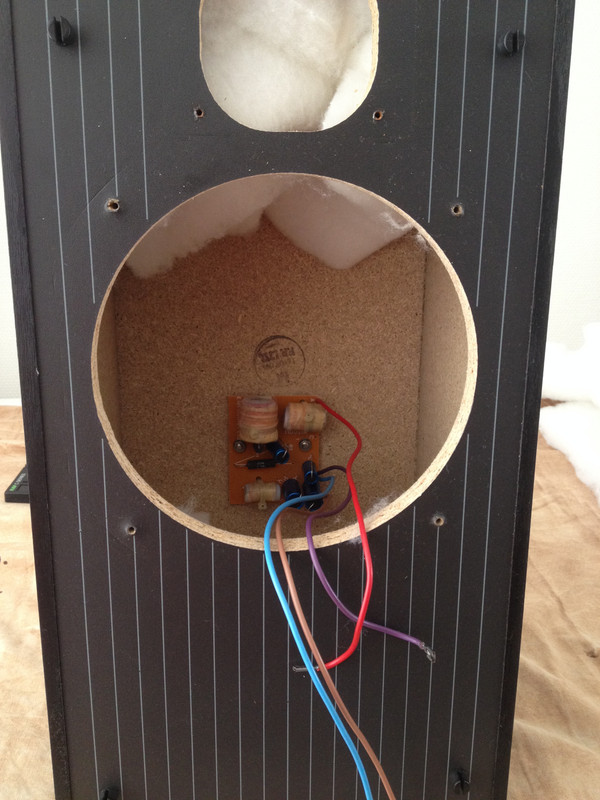
Description of situation when I opened the speaker:


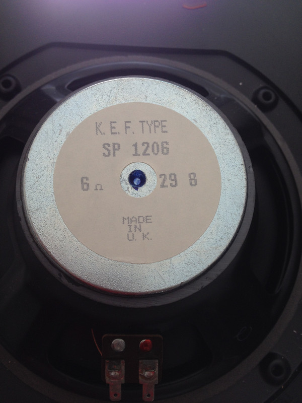
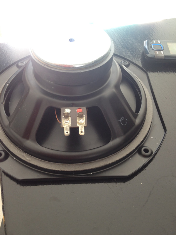
Woofer (see info in attached pictures) was attached with a red and a purple cable. Red cable was attached to the connector on the driver marked with red dot.


Click the image to open in full size.

Click the image to open in full size.


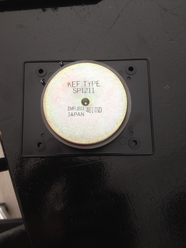
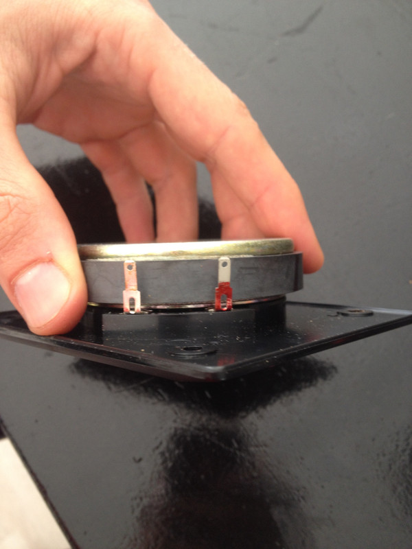
Tweeter was attached with purple and blue cable. Blue cable was attached to tweeter-connector with red dot.


Click the image to open in full size.

Click the image to open in full size.

I disconnected the woofer and the tweeter to do the measurements. I did not remove the cross-over from the back of the speakerbox. As far as I can see without removing the cross-over I do not see any sign of over-heating damage or any broken solder or loose cables.


Click the image to open in full size.

Resistance measurements:
Red binding post on outside red to red woofer cable: 1,0 ohm
Red binding post on outside red to purple woofer cable: infinite
Black binding post on outside red to red woofer cable: infinite
Black binding post on outside red to purple woofer cable: 0.6 ohm

Red binding post on outside red to blue tweeter cable: infinite
Red binding post on outside red to brown tweeter cable: infinite
Black binding post on outside red to blue tweeter cable: 0.6 ohm
Black binding post on outside red to brown tweeter cable: infinite

Between both connectors on woofer: infinite
Between both connectors on tweeter: 6,7 ohm

The conclusion I draw from these observations is that the woofer is probably broken (because of it's infinite resistance).

Can any of you shine any more light on my findings? Or maybe you have instructions for what more I should measure/investigate.
I did not dare to test the woofer or the tweeter in the other, still working, speaker, because I'm afraid that I could damage the undamaged electronics of the working speaker by introducing a faulty woofer/tweeter to it. Is this a true risk?


I'm looking in to this because I love to learn new things and also I hope to be able to repair/replace the broken part even if it costs some time/money.


Thanks in advance.

Beginner help requested

$
0
0
Hi All

I’m new to the forum, and have absolutely no experience with electronics.

Here’s my project:

I recently moved into an older house with an intercom system. I repurposed the control panel as a set of hooks for shopping bags etc. and would like to build a guitar amplifier using the guts. The original intercom had a phono in jack, a radio tuner, a speaker, lots of switches, plus the electronics (tubes and other stuff that I can’t yet identify, since I know absolutely nothing about electronics).

Can so help by sharing a source that will teach me the basics (how to identify the parts, and what I need to build a small guitar amplifier)?

Thanks!

Attached Images
File Type: jpeg 2463EB3F-5F12-404F-ACA9-EB029B138D7D.jpeg (22.5 KB)

questions about terminals

$
0
0
hi everyone
im having trouble researching what the affect of enlarging the conducting surfaces on speaker terminals would be, all of my google searches seem to focus on "capacitance of wire conductor" or "capacitors"(the actual component).
i'd like to know
(1what would be the affect of enlarging the surface area of the conductor ? pro's & con's
(2 would this potentially create a capacitor ? eg 2 large conductive plates separated by a small air gap.
(3 would the mass of the terminal affect the potential capacitance? larger terminal= more capacitance?
(4 could the shape of the terminal also have an affect ?

i have included a picture with a "poorly" drawn representation of what i'm trying to describe.
if you know the answers to any of these questions or could point me to some online resources that may help, i would be most grateful.

gaz

Attached Images
File Type: jpg 2.jpg (40.7 KB)

WTB 2SB1095 /2SD1586 pair in TO-220FP package

$
0
0
Looking for a pair or two of NEC 2SD1586 /2SB1095
transistors in TO-220F (FP) plastic package. If you have regular metal 2SB1095 that would be acceptable too.
Substitutes like BD954F/BD949F also accepted

Server hard drives

$
0
0
Any of you people that use a diy server for music and movies/ are you using regular hard drives or server hard drives ?
I’m asking this because I have over 50 dell and HP and seagate server hard drives
They use the sata input for data and power
I have ones from 360gb up to 2tb
So my question is this, is there a difference between server and pc hard drives? And if so, what is it ? I will post the model numbers of the drives I have , as I know someone will ask this. Thanks for any and all help

Crimping non-insulated quick disconnects / fastons

$
0
0
Hi,

I'm about to start my first amp builds (Neurochrome and Purifi based ones) and I've been researching a lot about crimping. Here is what I come up with:

1. For 4.8 mm / 6.3 mm quick disconnects / faston connectors, I'm looking to buy a reliable but affordable crimp tool. I'd crimp these non-insulated and cover them in head-shrink afterwards.
2. For everything else (JST, Molex, etc.) I'll buy pre-crimped wires, as it wouldn't make sense for me to buy the expensive tools needed to crimp these.

What crimp tool should I buy? A cheap, noname Aliexpress / Banggood kind of racheting tool or a simple but high quality non-racheting one?

I know many people buy professional tools here, but I'm only planning to use this for 10, maybe 20 times in total. I'm happy to invest $20-30 in a tool, but not $200+.

For example this is what looks really nice to me, about 20 EUR in Europe.
Knipex 97 21 215 B Crimping Plier


Click the image to open in full size.

The alternative would be some cheap racheting one like this:
4 in 1 ratchet crimper cable wire crimping plier electrical terminals plier tool kit Sale - Banggood.com
Click the image to open in full size.


or this:
Paron(R) jx-d5 multifunctional ratchet crimping tool wire strippers terminals pliers kit Sale - Banggood.com
Click the image to open in full size.

Then for the connectors, what should I look for? What brand, what material, locking mechanism, etc.? Is TE considered the best one?

Here is a filtered search I made at TME.eu about the ones I believe are fitting for me.

About the insulation, I'm thinking about using heat-shrink after crimping as I can make a more precise crimping this way.

What do you recommend?

Speaker Build Idea - F'AST Build

Viewing all 96743 articles
Browse latest View live


Latest Images