Re Broskie Four Way Series-Shunt Crossovers and resistance values.
This is an interesting article with a revised series network topology.
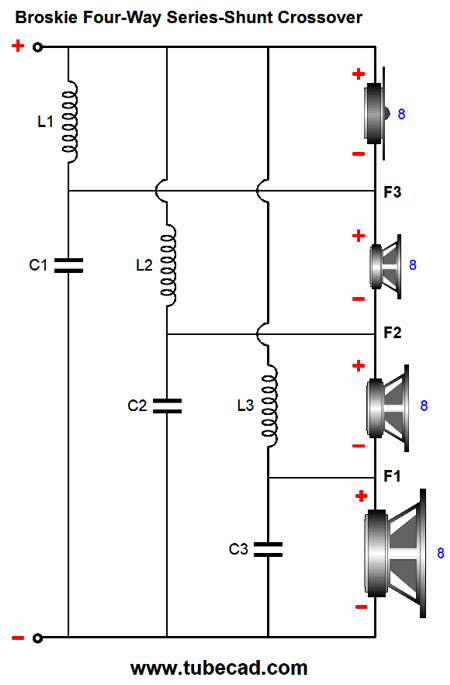
New Crossover Designs
All values in the article are all for 8 ohm values of R but what if you are using drivers with a different values of R?
Assume a 4 way design using a 4 ohm bass / 4 ohm upper bass / 4 ohm upper mids but an 8 ohm tweeter.
Am I right to assume that in theory the component value for the treble C1 will remain as calculated, but that all other component values will obviously change due to the 4 ohm R values?
Usually if impedance R halves then inductor values halve and capacitor values double. Is this the case here?
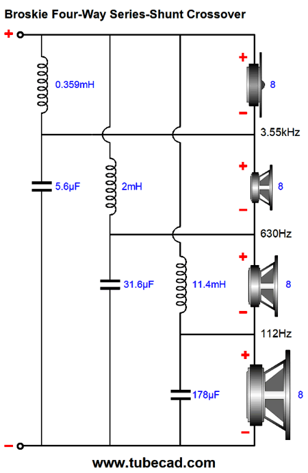
The only one that would not change would be the 8 ohm tweeter C1 which would still be a 5.6uF capacitor.
Math here
C1 = 159155/R/F3
C2 = 159155/R/F2
C3 = 159155/R/F1
L1 = 1k*R/(2*pi*F3)
L2 = 1k*R/(2*pi*F2)
L3 = 1k*R/(2*pi*F1)
Much fun
![Click the image to open in full size.]()
![Click the image to open in full size.]()
This is an interesting article with a revised series network topology.
New Crossover Designs
All values in the article are all for 8 ohm values of R but what if you are using drivers with a different values of R?
Assume a 4 way design using a 4 ohm bass / 4 ohm upper bass / 4 ohm upper mids but an 8 ohm tweeter.
Am I right to assume that in theory the component value for the treble C1 will remain as calculated, but that all other component values will obviously change due to the 4 ohm R values?
Usually if impedance R halves then inductor values halve and capacitor values double. Is this the case here?
The only one that would not change would be the 8 ohm tweeter C1 which would still be a 5.6uF capacitor.
Math here
C1 = 159155/R/F3
C2 = 159155/R/F2
C3 = 159155/R/F1
L1 = 1k*R/(2*pi*F3)
L2 = 1k*R/(2*pi*F2)
L3 = 1k*R/(2*pi*F1)
Much fun